
✨ This article was AI edited. Editorial responsibility: 3D-P.eu.
Produced with AI. This article was artificially generated. Editorial responsibility: 3D-P.eu.
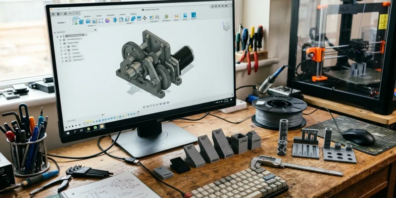
Traditional manufacturing methods—such as CNC subtractive milling and plastic injection molding—rely on draft angles, uniform wall sections, and continuous toolpaths. In contrast, 3D printing constructs components volumetrically from the bottom up. While additive manufacturing enables unprecedented geometric freedom, designing without adhering to core additive physics results in part delamination, excessive support scarring, curled overhangs, and loose fits. Incorporating rigorous DfAM guidelines ensures consistent first-time print success.
Core DfAM Rules for Material Extrusion (FDM) & Resin (SLA)
Below is a standardized engineering tolerance matrix for desktop and industrial additive systems:
| Geometric Feature | FDM / FFF Threshold | SLA / Resin Threshold | Design Recommendation |
|---|---|---|---|
| Maximum Self-Supporting Overhang | 45° from vertical (The 45° Rule) | 30° from vertical | Use 45° chamfers instead of horizontal shelves to eliminate supports |
| Maximum Unsupported Bridge | 10.0 mm (Standard cooling) | Unsupported bridges not recommended | Add teardrop ceilings or arched transitions for internal voids |
| Minimum Supported Wall Thickness | 0.8 mm (2x 0.4mm nozzle perimeters) | 0.4 mm | Design walls as integer multiples of your slicing extrusion width |
| Moving Interlocking Clearance | 0.40 mm – 0.50 mm | 0.15 mm – 0.20 mm | Prevents fusion on print-in-place bearings and hinges |
| Minimum Embossed / Debossed Detail | 0.6 mm width, 0.4 mm height | 0.1 mm width, 0.1 mm height | Orient fine text vertically along the Z-axis for crispest definition |
5 Fundamental DfAM Principles Every CAD Designer Must Apply
1. The 45-Degree Self-Supporting Rule
Each extruded thermoplastic layer relies on the underlying layer for structural support. As the angle of an overhang exceeds 45° relative to the vertical Z-axis, the outer bead loses contact area, drooping into unsightly strings. By designing internal chamfers and organic fillets at ≤45°, complex functional geometries print cleanly without wasting material on disposable supports.
2. The Teardrop Hole Geometry
Circular horizontal holes printed parallel to the build plate inevitably suffer from sagging roof perimeters. Replacing circular bores with an arched teardrop profile (a circle with a 45° triangular apex) maintains self-supporting angles throughout the entire bore, eliminating the need for post-print drilling.
3. Minimizing Stress Concentrations with Generous Fillets
Sharp internal 90-degree corners act as microscopic stress concentrators that amplify notch sensitivity under mechanical shock loads. Applying continuous 1.5 mm to 3.0 mm corner fillets distributes tensile loads across adjacent toolpaths, dramatically increasing part fatigue life.
4. Anisotropic Orientation Strategy
Because FDM parts exhibit 30% to 50% lower tensile strength along the vertical Z-axis compared to the horizontal X/Y plane, always orient your part so that primary operational bending or pulling stresses align parallel to the continuous toolpath lines.
5. Print-in-Place Assembly Clearances
Designing articulating linkages, ball joints, or captive gears in a single print cycle requires precise radial clearances. For a standard 0.4 mm nozzle setup, maintain a radial air gap of at least 0.45 mm between sliding surfaces to prevent polymer fusion during thermal expansion.
Frequently Asked Questions
Why do horizontal holes print smaller than designed in CAD?
As molten plastic cools and solidifies, thermal contraction pulls the circular perimeter inward toward the center of the arc. Additionally, polygon approximation in STL file exports converts circles into inscribed polygons. Add +0.2 mm to +0.3 mm clearance on horizontal CAD holes to compensate.
What is the best infill pattern for structural strength?
Gyroid, 3D Honeycomb, and Cubic infill patterns provide balanced three-dimensional isotropic load distribution. Gyroid is particularly favored because it prints without nozzle crossing and provides identical tensile resistance in all directions.
How can you avoid the ‘elephant’s foot’ on the first layer?
Elephant’s foot is the slight outward bulging of the bottom layer caused by bed squish and high build plate temperatures. Add a small 0.5 mm x 45° chamfer to the bottom edge of your CAD model to absorb the initial layer spread.
Get our latest guides, news, and insights highlighted in your Google Search & AI Overviews.


 — Engineering Rules | 3D-P.eu)