
✨ This article was AI edited. Editorial responsibility: 3D-P.eu.
Designing a custom smartphone case is one of the most rewarding and practical functional 3D printing projects. However, smartphones feature tight ergonomic curves, delicate button actuation tolerances, and precise camera bump geometries that leave zero margin for dimensional guesswork.
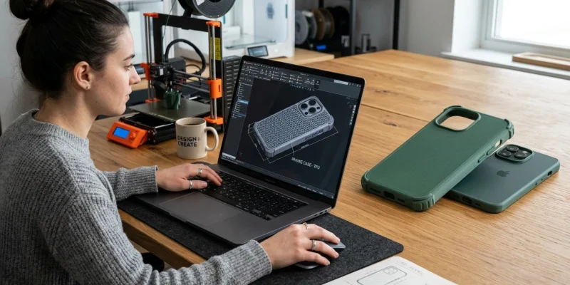
This comprehensive engineering tutorial guides you step-by-step through designing a professional, production-grade iPhone protective case using parametric CAD software (such as Fusion 360, Onshape, or SolidWorks) and preparing it for flawless additive manufacturing.
Step 1: Obtain Official Dimensional Specifications
Never rely on measuring your physical phone with manual calipers alone. Glass edge bevels, chamfers, and lens protruberances are nearly impossible to capture accurately by hand.
- Apple Accessory Design Guidelines (ADG): Apple publishes a free 300+ page technical engineering document containing dimensioned 2D orthographic blueprints for every iPhone model (including exact corner radii, speaker hole centerlines, microphone keep-out zones, and camera bump offsets).
- CAD Step Files: Alternatively, download dimensionally verified 3D STEP dummy models from trusted engineering repositories (GrabCAD or Printables) to serve as a parametric reference body.
| Material Selection | CAD Clearance Offset | Lip Overhang Geometry | Recommended Slicer Settings |
|---|---|---|---|
| Flexible TPU (95A) | +0.15 mm to +0.25 mm | 0.8 mm wrap-around screen bezel lip | 20?30 mm/s speed, direct drive extruder, 100% infill |
| Rigid Polycarbonate / PETG | +0.35 mm to +0.50 mm | Snap-fit detent bumps with relief slots | 3 perimeters, 0.2mm layer height, fan at 40% |
| Hybrid Dual-Material | +0.20 mm | Rigid PC backplate with co-molded TPU perimeter | Multi-material IDEX or toolchanger printer |
Step 2: Parametric Modeling Workflow in CAD
1. Create the Phone Clearance Envelope
Import the official phone geometry into your CAD software or sketch the base rectangle matching your phone’s length, width, and corner fillet radii. Extrude the solid phone body, adding the exact edge fillet radius (typically 8mm to 10mm corner fillet depending on the model generation).
2. Shell the Protective Perimeter
Use the Offset or Shell command to create the wall thickness:
- Wall Thickness: 1.6 mm to 2.2 mm provides the ideal balance between drop shock absorption and pocketable slimness.
- Backplate Thickness: 1.4 mm to 1.8 mm (ensure compatibility with Qi and MagSafe wireless charging coils, which lose efficiency rapidly above 2.0 mm thickness).
3. Model the Camera Bump & Screen Protection Lips
To protect delicate sapphire camera lenses and OLED screen glass from drops on rough pavement:
- Screen Protection Bezel: Extend the front bezel lip 1.0 mm to 1.2 mm above the display glass plane.
- Camera Island Ring: Model a raised protective ridge 1.5 mm higher than the camera lens caps with a 45? chamfer to eliminate overhang support requirements during 3D printing.
4. Cut Port Openings and Tactile Button Geometry
Nothing ruins a 3D-printed phone case faster than a USB-C cable that won’t plug in because the cutout is too small:
- Charging Port: Add generous clearance around the Lightning / USB-C port (at least 13 mm x 7 mm) to accommodate oversized third-party charging plugs.
- Speaker & Microphone Grilles: Mirror speaker slot cutouts along the bottom edge, leaving a solid 2mm dividing bridge to prevent tear-out in TPU.
- Tactile Buttons: Model flexible button covers by adding a 0.6 mm recessed relief groove around three sides of each volume and power button, allowing them to click with light finger pressure.
Step 3: Slicing & 3D Printing Your Custom Case
Printing functional phone cases requires proper material and slicer configuration:
- Material Choice: TPU 95A is the undisputed gold standard for 3D printed phone cases. It provides rubber-like flexibility, drop impact damping, and will never crack or snap during installation.
- Orientation: Place the case flat on its backplate on the build plate. This ensures smooth, attractive surface texture on the rear and eliminates internal supports.
- Perimeters / Walls: Set slicer perimeters to 4 or 5 walls. This creates a solid, rubbery perimeter ring with zero internal air voids for maximum tear strength.
Advanced Design Features: Honeycomb Infill & MagSafe Cavities
Transforming a generic phone bumper into a luxury, high-performance accessory requires sophisticated CAD modeling techniques:
1. Parametric Weight Reduction & Heat Dissipation Cutouts
Smartphones generate substantial heat during fast wireless charging and intensive gaming. Solid plastic cases insulate the device, causing thermal throttling:
- Hexagonal / Voronoi Perforations: Cut a decorative hexagonal honeycomb mesh through the rear backplate. In Fusion 360 or Onshape, create a single 4mm hexagon sketch, apply a rectangular or circular pattern, and use the Extrude Cut feature with a 1.2mm border offset.
- Internal Shock-Absorbing Ribs: Add tiny 0.4mm raised air-pocket ribs along the inside perimeter corners. These ribs act as sacrificial crumple zones that absorb kinetic impact if the phone lands on an edge.
2. Embedding Integrated MagSafe Magnet Rings
To ensure robust compatibility with Apple MagSafe chargers, wallets, and car phone mounts:
| MagSafe Dimension Parameter | Standard Specification | CAD Cavity Recommendation |
|---|---|---|
| Outer Ring Diameter | 54.0 mm | 54.4 mm (+0.4mm clearance) |
| Inner Ring Diameter | 46.0 mm | 45.6 mm |
| Alignment Magnet Notch | Vertical slot at 6 o’clock position | 6.0 mm x 3.0 mm rectangular slot |
| Magnet Thickness | 0.8 mm ? 1.0 mm | 1.0 mm depth recess with adhesive backing |
Frequently Asked Questions
Can PLA be used for a 3D printed iPhone case?
Standard PLA is not recommended for snap-fit phone cases because it is rigid and brittle; attempting to force the phone into a rigid PLA shell often snaps the corners or scratches the phone bezel. Flexible TPU or resilient PETG is far superior.
Will a 3D printed case interfere with wireless MagSafe charging?
If the backplate thickness is kept between 1.2 mm and 1.6 mm, standard Qi and MagSafe wireless charging work through TPU and PLA without issue. For magnetic car mounts, you can embed an adhesive MagSafe ferrite ring into a 0.8 mm recessed circular cavity in CAD.
Get our latest guides, news, and insights highlighted in your Google Search & AI Overviews.


