
✨ This article was AI edited. Editorial responsibility: 3D-P.eu.
Produced with AI. This article was artificially generated. Editorial responsibility: 3D-P.eu.
Whether you operate a desktop Cartesian bedslinger, an enclosed CoreXY fabrication cell, or an industrial powder-bed metal system, the 3D printer stage represents the mechanical foundation of dimensional accuracy. An unstable, unlevel, or thermally warped build stage introduces Z-banding, layer skew, first-layer failure, and inconsistent part tolerances.
In this technical engineering guide, we dissect the anatomy of modern 3D printer stages, compare kinematic mounting methodologies, evaluate heated bed substrates, and explain how to optimize stage stiffness for high-acceleration printing.
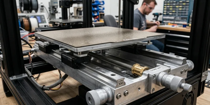
Anatomy of a Precision 3D Printer Stage
A professional 3D printer build stage comprises several tightly integrated mechanical sub-assemblies:
| Component Layer | Engineering Function | Standard Materials | Key Tolerance Requirements |
|---|---|---|---|
| Sub-Carriage Frame | Transmits motion from Z/Y axis linear rails; resists torsional bending | Anodized 6061-T6 Aluminum, Carbon Fiber Tube, Sheet Steel | High rigidity-to-weight ratio; zero flex under acceleration |
| Kinematic Mounts | Decouples thermal expansion of heated plate from rigid frame | Hardened stainless ball-in-groove, brass bushings, spherical washers | Constrains exactly 6 degrees of freedom without over-constraint |
| Tooling Substrate | Provides mathematically flat foundation across thermal operating range | Cast Aluminum Tooling Plate (MIC-6 or Alca 5) | Thickness 6mm ? 10mm; flatness < 0.05 mm across 300x300mm |
| Heating Element | Delivers uniform radiant thermal energy to melt/anneal polymer bases | High-wattage Silicone AC Mat (220V/110V) or Etched Copper PCB | Thermal uniformity within ?2?C across entire active build area |
| Build Surface | Interchangeable textured or smooth interface for part adhesion | Spring steel with Textured PEI, Garolite (G10), PEX, Borosilicate glass | High magnetic pull strength (N42SH neodymium magnets rated to 120?C) |
Kinematic Bed Mounting vs. Rigid 4-Corner Screws
Traditional budget 3D printers bolt the build stage down at four corners using thumbscrews and compressed die springs. While cheap to manufacture, 4-corner rigid mounting creates catastrophic thermal distortion:
The Problem of Thermal Over-Constraint
When aluminum heats from 20?C to 110?C for engineering filament printing, it expands significantly ($23 imes 10^{-6} ext{ K}^{-1}$). On a 300 mm aluminum bed, thermal expansion increases the plate dimensions by over 0.6 mm. If the four corners are clamped rigidly to a cold steel carriage, the expanding plate has nowhere to go but to buckle upwards or downwards like a diaphragm, causing the center to warp by up to 0.4 mm.
The Kinematic Tri-Point Solution
Modern high-end printers (such as Voron, RatRig, and industrial flagships) utilize True Kinematic 3-Point Mounting:
- Fixed Anchor: One spherical ball rests in a conical cup, fixing the X, Y, and Z position.
- V-Groove Guide: A second spherical ball rests in a linear V-groove oriented radially, allowing expansion along only one axis.
- Flat Plane: The third ball rests on a flat polished surface, preventing rotation while allowing unrestricted 2D thermal expansion.
Under kinematic constraint, the build plate remains completely flat regardless of whether it is operating at 20?C or 150?C, eliminating the need to recalibrate automatic bed leveling meshes between cold and hot states.
Cast Tooling Plate vs. Stamped Rolled Aluminum
Budget 3D printer beds are fabricated from rolled sheet aluminum. Rolled aluminum contains high internal residual stresses from the rolling mill. As soon as the bed is heated, these internal stresses relax unpredictably, causing the bed to taco or warp permanently.
In contrast, Cast Aluminum Tooling Plates (such as MIC-6, Alimex, or Alca 5) are cast in thick blocks and precision-milled on both sides. Cast tooling plates feature zero internal stress and maintain strict flatness tolerances (typically within 0.05 mm across an entire 350 mm plate), providing the ultimate foundation for first-layer perfection.
Kinematic Alignment & Thermal Drift Compensation
Modern closed-loop 3D printers incorporate sophisticated algorithms to measure and counteract stage movement during active thermal cycles:
| Compensation Technique | Sensor / Hardware Mechanism | Mathematical Correction Method | Repeatability Tolerance |
|---|---|---|---|
| Bicubic Mesh Bed Leveling | Inductive probe, BLTouch, or Beacon Eddy Current | Dynamic Z-axis motor micro-stepping during X/Y interpolation | ?0.005 mm |
| Thermal Bed Expansion Mapping | Thermocouples embedded at bed center and edge perimeters | Software thermal expansion factor scaling Z coordinates over time | ?0.010 mm |
| Independent Multi-Z Tramming | 3 or 4 independent Z-axis stepper motors (CoreXY Voron / RatRig) | Automatic pitch and roll angular leveling via kinematic probe readings | ?0.002 mm angular runout |
Upgrading Your Desktop 3D Printer Stage: The Essential Checklist
If you are rebuilding or upgrading a stock printer stage for high-speed Klipper printing or engineering polymer capabilities, follow this hardware upgrade roadmap:
- Step 1: Replace Stamped Carriage with Milled 6061 Aluminum: Eliminate stamped steel carriage plates that bend when heated. A 4mm milled aluminum Y-carriage reduces reciprocating inertia by up to 35%.
- Step 2: Install Precision Linear Rails (MGN12H): Replace rubber POM V-slot wheels with genuine precision linear guide rails. Linear rails eliminate carriage wobble and maintain strict vertical rigidity under heavy nozzle acceleration.
- Step 3: High-Temperature Thermal Insulation: Bond a 10mm closed-cell ceramic or silicone foam insulation pad to the underside of the aluminum bed plate. This cuts heating time by 50% and prevents ambient air drafts from creating localized cold zones on the build surface.
Frequently Asked Questions
What is the difference between a Cartesian bedslinger stage and a CoreXY stage?
In Cartesian bedslingers (like the Ender 3 or Prusa MK4), the stage translates back and forth rapidly along the Y-axis, which limits printing speed due to high moving mass. In CoreXY printers (like the Bambu Lab X1 or Voron 2.4), the stage either moves purely down along the Z-axis or remains stationary, allowing significantly higher acceleration.
Why do industrial printers use high-voltage AC bed heaters?
AC silicone heaters (operating at 120V or 230V directly from mains through a solid-state relay) deliver 500W to 1000W of power, heating massive 8mm cast aluminum stages from ambient to 100?C in under 2 minutes without burdening the 24V DC printer power supply.
Get our latest guides, news, and insights highlighted in your Google Search & AI Overviews.


![Why Use a 3D Printer Part Cooling Fan? [Performance Benefits Explained]](https://3d-p.eu/wp-content/uploads/2025/03/175-why-use-a-3d-printer-part-cooling-fan-performance-benefits-explained.jpg "Why Use a 3D Printer Part Cooling Fan? [Performance Benefits Explained]")
![How to Build an A8 3D Printer? [DIY Assembly Guide]](https://3d-p.eu/wp-content/uploads/2025/03/50-how-to-build-an-a8-3d-printer-diy-assembly-guide.jpg "How to Build an A8 3D Printer? [DIY Assembly Guide]")
