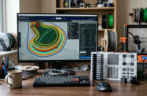
3D Printer Slicer Settings — Speed, Flow & Retraction | 3D-P.eu
3D printer slicer settings are the mathematical parameters and machine instructions configured within slicing software (OrcaSlicer, PrusaSlicer, …
Slicing Software analyzes the algorithms, infill mathematics, support generation strategies, and toolpath optimization parameters that govern 3D printing slicing engines.
Engineering guide to calibrating outer wall speeds, maximum volumetric extrusion limits, fan cooling curves, and z-hop behavior.
Head-to-head comparison of OrcaSlicer, PrusaSlicer, Ultimaker Cura, and Bambu Studio evaluating UI workflow and calibration tools.
Configuring custom machine profiles, start/end G-code sequences, custom build plate dimensions, and baud rates in Ultimaker Cura.
Automated print queue management, cloud slicing integration, plate packing algorithms, and remote farm monitoring utilities.
Slicing software converts three-dimensional mesh models into precise numerical control sequences (G-code) tailored to specific kinematic hardware. The toolpath generation pipeline calculates discrete planar perimeters, determines solid floor and ceiling fills, computes interior infill patterns, and constructs sacrificial support pillars. The sequence of perimeter deposition fundamentally impacts accuracy: printing the outer perimeter first (outside-in) yields maximum dimensional fidelity on external diameters, while inside-out sequencing provides superior cantilever support on steep overhang angles.
Infill geometry has evolved from simple rectilinear grids to mechanically optimized isotropic patterns. While 2D infill patterns (rectilinear, grid, triangular) exhibit directional weakness along orthogonal planes, 3D Gyroid infill provides continuous, non-planar isotropic resistance to shear and torsional forces in all axes. Furthermore, Gyroid infill eliminates intersecting extrusion tracks on the same layer, completely preventing nozzle dragging and high-speed knocking during travel moves.
Support generation algorithms represent another major frontier in slicing technology. Traditional linear pillar supports consume substantial material and bond aggressively to downward-facing surfaces. Organic (Tree) supports branch gracefully from the build plate around delicate geometry, contacting the model only at minimal branch tips. This drastically reduces support print time and raw material consumption by up to 65% while leaving clean, easily removable contact scars.
| Infill Pattern | Structural Geometry | Shear Strength Isotropy | Best Application |
|---|---|---|---|
| Gyroid Infill | Continuous 3D triply periodic minimal surface | 100% Isotropic (Equal in all axes) | Functional brackets, enclosures, vibration dampers |
| Rectilinear | Alternating 90° single-pass parallel lines | Moderate (Anisotropic along 45° planes) | Fast prototyping, low material cost, simple models |
| Honeycomb (Hexagonal) | 2D interlocking hexagonal tessellation | High compressive strength on vertical axis | Lightweight structural cores, aircraft panels |
| Concentric | Progressive nested offsetting from perimeters | Flexible, low internal shear resistance | Elastomeric TPU phone cases, flexible bellows |
| Adaptive Cubic | Octree variable density (dense near surfaces) | High efficiency strength-to-weight | Large sculptures, industrial molds, bulk parts |
Standard supports build straight vertical towers directly beneath every overhang, often requiring extensive contact with the model below. Tree supports sprout like tree branches from the build plate, curving around the model to support overhangs without touching lower vertical walls, making them easier to snap off cleanly.
Traditional slicing engines used fixed line widths, leaving gaps or requiring ugly gap-fill moves on walls with non-integer nozzle widths. The Arachne perimeter generator dynamically varies extrusion line width continuously, producing solid, gap-free walls with crisper corner geometry.
Maximum Volumetric Speed (measured in mm³/s) is a protective safety ceiling defined by: Layer Height × Extrusion Width × Print Speed. It caps toolhead speed so that the total volume of plastic demanded per second never exceeds the physical melting capacity of the hotend, eliminating high-speed under-extrusion.