
✨ This article was AI edited. Editorial responsibility: 3D-P.eu.
Produced with AI. This article was artificially generated. Editorial responsibility: 3D-P.eu.
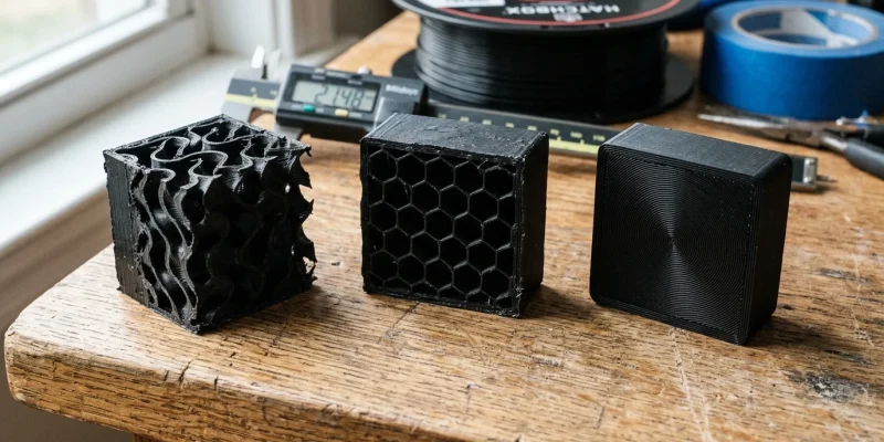
In fused deposition modeling (FDM), solid 100% infill is rarely necessary and often counter-productive, causing internal thermal stresses, warping, and excessive print times. Infill acts as the internal structural skeleton of your part. Selecting the optimal infill geometry and density percentage allows you to achieve maximum mechanical tensile and compressive strength while minimizing material consumption and print duration.
Head-to-Head Comparison: Popular 3D Printing Infill Patterns
| Infill Pattern | Stress Characteristics | Print Speed & Nozzle Wear | Best Used For |
|---|---|---|---|
| Gyroid | Isotropic (Equal strength in X, Y, and Z axes) | Smooth continuous motion; zero nozzle intersection clicks | Functional engineering parts, liquid-tight containers, flexible TPU |
| Cubic / 3D Honeycomb | High multi-directional shear and compressive strength | Moderate; occasional line crossovers | Structural brackets, load-bearing mounts, drone arms |
| Grid | High vertical compression; poor shear resistance | High speed, BUT nozzle crosses printed lines on every layer | Simple cosmetic boxes (Not recommended for high-speed printers) |
| Rectilinear / Lines | Moderate 2D tensile strength | Fastest print speed; no line crossing | Rapid prototyping, visual display models, draft prints |
| Concentric | Bends along outer contours; flexible | Moderate speed | TPU phone cases, flexible seals, circular aesthetic tops |
The Golden Rule of Part Strength: Perimeters vs. Infill Density
Mechanical testing consistently proves a counter-intuitive principle in additive engineering:
Increasing perimeter wall count from 2 to 4 increases part bending strength by over 150%, whereas increasing infill density from 20% to 50% increases strength by only 25% while doubling print time.
For maximum strength-to-weight efficiency, always add perimeter wall loops (3–5 perimeters) and maintain infill density between 15% and 25% using a 3D isotropic pattern like Gyroid or Cubic.
Why Gyroid Infill is the Modern Standard
The Gyroid pattern is a triply periodic minimal surface discovered by NASA mathematician Alan Schoen. In 3D printing, Gyroid offers three unique mechanical advantages:
- Continuous Non-Intersecting Toolpaths: The print head never crosses an already-extruded line on the same layer, completely preventing nozzle collisions, knocking parts off the bed, and extruder clicking at high travel speeds.
- Isotropic Flex: When printing flexible filaments like TPU (95A), Gyroid provides uniform, spring-like rebound in every direction without creasing.
- Drainage Channels: The open interconnected chambers allow resin or trapped washing solvents to drain completely when printing hollow models.
Frequently Asked Questions
Why does Grid infill make a loud clicking noise on fast printers?
Grid infill extrudes lines that cross directly over each other at 90-degree intersections on the exact same layer height. As the nozzle passes over the hardened intersecting plastic, it physically collides, causing clicking noises and potential layer shifts.
What infill percentage is ideal for functional brackets?
For functional brackets and mounts, use 4 to 5 perimeter wall loops combined with 20% to 30% Gyroid or Cubic infill. This provides maximum rigidity and impact resistance.
Does 100% infill make parts indestructible?
Not necessarily. Solid 100% infill traps significant thermal stress as large volumes of polymer cool, frequently causing corner warping and layer delamination. Multi-perimeter parts with 40% Gyroid infill often exhibit superior impact toughness over solid 100% prints.
Get our latest guides, news, and insights highlighted in your Google Search & AI Overviews.


