3D Printer Stage Explained: Build Platforms & Kinematic Mechanics
3D Printer Stage: In additive manufacturing, the 3D printer stage (also termed the build stage or z-axis …
Hardware Components covers the electromechanical anatomy, thermal sub-assemblies, motion kinematics, and electronic control modules that comprise functional 3D printing systems.
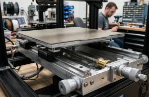
Detailed breakdown of Z-axis stage mechanics, lead screw pitch versus ball screws, anti-backlash nuts, and heated bed thermal expansion.
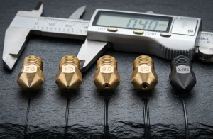
Fluid dynamics and extrusion geometry analysis demonstrating how nozzle orifice size governs backpressure, layer height limits, and print time.
Comprehensive guide to vertical motion control, microstepping resolution, Z-wobble decoupling mechanisms, and layer consistency.
Electrical safety and mainboard offloading tutorial for external high-current bed heater control, preventing motherboard terminal burns.
The mechanical reliability of any 3D printer hinges on the symbiotic precision of its electromechanical subsystems. At the heart of thermoplastic deposition is the extruder assembly, classified into Direct Drive and Bowden configurations. Direct drive mounts the stepper motor directly above the hotend, minimizing the filament constrained path to under 50mm. This tight constraint dramatically improves pressure advance responsiveness, eliminates retractive stringing, and allows reliable feeding of flexible elastomers (TPU/TPE). Bowden systems relocate the heavy motor to the frame, reducing toolhead mass for faster speeds at the expense of higher retraction distances and greater hysteresis.
The hotend assembly itself requires meticulous thermal engineering. Comprising a heater block, temperature sensor (thermistor, thermocouple, or PT1000 RTD), heat break, and heat sink, its primary objective is establishing an abrupt temperature differential over a narrow geometric zone. Bi-metallic heat breaks pairing copper for rapid axial conductivity with thin-walled titanium or tungsten to choke conductive transfer represent the modern standard for engineering polymers operating up to 300°C.
Motion transmission relies on NEMA 17 or NEMA 14 stepper motors coupled to GT2 fiberglass-reinforced neoprene timing belts or precision ground lead screws. Stepper driver technology has evolved from rudimentary A4988 choppers to advanced Trinamic silent drivers (TMC2209, TMC2240) utilizing StealthChop silent pulse-width modulation and SpreadCycle dynamic torque control, complete with sensorless homing via back-EMF StallGuard telemetry.
| Component Sub-Assembly | Key Specifications | Critical Function | Upgrade / Maintenance Standard |
|---|---|---|---|
| Hotend Heat Break | Bi-metallic (Copper/Titanium), M6/M7 thread | Isolates melt zone from cold sink | Inspect for thermal paste degradation every 500 print hours |
| Extruder Drive Gears | Dual hardened steel gears (50+ HRC) | Provides positive bite without chewing filament | Clean filament debris and re-torque tensioner weekly |
| Z-Axis Lead Screw | T8x8 or T8x4 stainless steel with POM nut | Converts rotation to vertical linear movement | Grease with PTFE-based lubricant; align motor couplers |
| Mainboard Stepper Drivers | TMC2209 / TMC2240 with UART control | Microstepping interpolation up to 256 steps | Verify VREF current tuning to prevent stepper overheating |
| Heated Bed Platform | Cast aluminum tooling plate with PEI sheet | Provides uniform thermal base up to 110°C | Clean PEI surface with 99% isopropyl alcohol between jobs |
Brass has superior thermal conductivity but wears out rapidly when printing abrasive composite filaments (carbon fiber, glass fill, glow-in-the-dark). Hardened steel resists abrasive erosion, maintaining exact orifice diameter over hundreds of kilograms of composite filament.
High-wattage heated beds draw between 10A and 15A of current. In older budget printers, running this current through the mainboard’s small onboard transistors and screw terminals can cause severe overheating or burnt connectors. An external MOSFET routes high current directly from the power supply.
Z-banding is caused by bent lead screws, misaligned motor couplers, or cyclical bed heating thermal expansion. Upgrading to flexible spider couplers, anti-backlash POM nuts, or Oldham decouplers isolates screw wobble from the build stage.